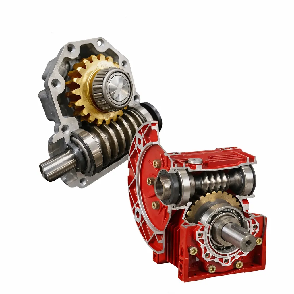
Instalación de reductores de engranajes helicoidales: Guía paso a paso para ingenieros
Una instalación correcta reductor de engranajes helicoidales reductor de engranajes helicoidales Funcionará durante años sin problemas. La misma unidad, instalada con los atajos comunes que suelen tomar muchos equipos de campo, puede fallar en cuestión de meses, no por la calidad del producto, sino por errores de instalación que se pueden evitar por completo con el procedimiento correcto.
Antes de comenzar: Comprobaciones previas a la instalación que no se pueden omitir
Los errores de instalación casi siempre se cometen en los primeros 20 minutos, mientras el instalador aún se está familiarizando con la unidad. Una verificación sistemática previa a la instalación para una reductor de engranajes helicoidales Tarda menos de 10 minutos y evita la mayoría de los problemas de puesta en marcha.
Lista de verificación para desempaquetar
☑ Verificación de la placa de características: el número de modelo, la relación y la configuración del eje de salida coinciden con el pedido.
☑ Diámetro del eje de salida y dimensiones del chavetero medidos según el plano.
☑ El patrón de orificios para pernos de brida/pie coincide con la interfaz de la máquina.
☑ Sin grietas visibles en la carcasa, sin sellos dañados, sin superficie del eje dañada.
☑ Tapón de ventilación presente y no obstruido (verificar si hay cinta de embalaje)
☑ Todo el hardware incluido: tornillos de montaje, cualquier soporte de brazo de torsión especificado
☑ Se incluye manual de instalación o plano dimensional.
Confirmación del nivel de aceite
Mayoría reductores de engranajes helicoidales se envían con aceite lleno reductores de engranajes helicoidales se envían con aceite lleno hasta el nivel de montaje horizontal estándar. Antes de la instalación, confirme el reductor de engranajes helicoidales El nivel de aceite es el correcto para la orientación de montaje prevista; las distintas orientaciones requieren diferentes niveles de llenado, y usar un nivel incorrecto es una causa común de problemas de lubricación prematuros. Consulte la tabla de orientación en la sección 5 de esta guía.
Herramientas necesarias y por qué la llave dinamométrica no es opcional.
Llave dinamométrica (imprescindible): Los pernos de montaje con un par de apriete insuficiente permiten que reductor de engranajes helicoidales La carcasa se flexiona bajo carga, abriendo gradualmente una abertura en la superficie de montaje y, finalmente, provocando fugas en el sello. Los pernos apretados en exceso en las carcasas de aluminio pueden agrietar el saliente alrededor del orificio del perno. Ninguna de estas fallas es visible de inmediato; ambas se previenen por completo utilizando una llave dinamométrica calibrada con los valores especificados.
Extractor/herramienta de instalación de rodamientos (imprescindible): Los acoplamientos, poleas y piñones deben colocarse a presión o a tirones sobre el eje sin fin; nunca se deben golpear con un martillo. Los golpes de martillo transmiten cargas de impacto directamente a los cojinetes del eje, fracturando la pista interior del cojinete o aumentando permanentemente la holgura. Un extractor mecánico sencillo o una prensa hidráulica eliminan este problema por completo.
Indicador de cuadrante / base magnética: Es necesario verificar la alineación del eje en cualquier instalación de acoplamiento directo. Los errores de alineación superiores a 0,1 mm radiales o 0,05 mm/100 mm angulares generan cargas en el eje que no se tienen en cuenta en la selección del rodamiento y reducen significativamente su vida útil.
Termómetro infrarrojo: Para la monitorización de la temperatura durante la puesta en marcha. No es necesaria para la instalación en sí, pero sí para la verificación de la puesta en marcha. Basta con un termómetro infrarrojo básico ($30–50).
Conexión del extremo de entrada: Acoplamiento del motor
Brida IEC de montaje directo (serie NMRV)
Serie NMRV reductores de engranajes helicoidales Con entrada de brida IEC, se acepta el montaje directo del motor sin acoplamiento. El eje del motor se inserta en el orificio de entrada del eje sin fin (conexión con chaveta). Procedimiento:
1. Confirme que el diámetro del eje del motor coincida con el diámetro del orificio de entrada del reductor (dentro de la tolerancia h6/H7).
2. Aplique una fina capa de compuesto antigripante al eje del motor. Esto evita que se atasque por corrosión durante el desmontaje posterior.
3. Inserte el eje del motor en el orificio de entrada del reductor. La chaveta debe asentarse completamente en la ranura. No fuerce; si encuentra resistencia, verifique el diámetro del eje y la alineación de la ranura antes de continuar.
4. Apriete los pernos de brida IEC siguiendo un patrón en forma de estrella al par de apriete especificado (consulte la tabla del fabricante para conocer los tamaños de pernos M8–M12).
Conexión de acoplamiento flexible (serie WP)
Alineación radial: Monte un indicador de cuadrante en el eje del motor, tocando el borde de la mitad del acoplamiento en el reductor de engranajes helicoidales Eje helicoidal. Gire el eje del motor 360°. Excentricidad máxima: 0,05 mm para acoplamiento estándar, 0,02 mm para acoplamiento servo de precisión.
Alineación angular: Utilice un calibrador de espesores en cuatro posiciones de 90° alrededor del espacio de acoplamiento. Desviación angular máxima: 0,05 mm por cada 100 mm de diámetro de acoplamiento.
Si la alineación está fuera de tolerancia: Calce las patas del motor o ajuste la posición de montaje del reductor. No acepte desalineaciones y añada un elemento de acoplamiento flexible para "absorberlas"; los elementos flexibles compensan la dilatación térmica, no los errores de instalación.

Entrada de transmisión por correa y transmisión por cadena: límite de carga de la suspensión: Al instalar una polea o piñón en el eje de entrada del tornillo sin fin, la tensión de la correa o cadena ejerce una fuerza radial sobre el eje. Esta fuerza no es insignificante: una correa trapezoidal en una polea de 100 mm de diámetro que transmite 2 kW a 1440 rpm puede generar entre 300 y 500 N de fuerza radial sobre el eje. Consulte la hoja de datos para conocer la fuerza radial máxima admisible (Fr₁) para el eje de entrada y confirme que la tensión de la correa calculada sea inferior a este límite. Las cargas en voladizo que superen Fr₁ reducirán considerablemente la vida útil de los rodamientos, a veces hasta 4 u 8 veces.
Conexión del extremo de salida: Equipo accionado
Instalación de eje de salida sólido
Montaje de piñones, poleas o mitades de acoplamiento en el eje de salida sólido del reductor de engranajes helicoidales Sigue el mismo principio que en el extremo de entrada: utilice una prensa o extractor, nunca un martillo. Tras asentar el componente, fíjelo con el perno o la tuerca del extremo del eje al par de apriete correcto e instale una arandela de seguridad o un compuesto fijador de roscas adecuado para el nivel de vibración de la aplicación.
La carga radial (Fr₂) del eje de salida que figura en la hoja de datos supone que la carga se aplica en el punto medio de la extensión del eje. Si la carga se aplica en el extremo del eje (máximo voladizo), el valor admisible de Fr₂ se reduce en 20–30%. Confirme qué condición se aplica a su instalación.
Instalación del eje de salida hueco
Las variantes de eje hueco de la serie NMRV se deslizan directamente sobre el eje del equipo accionado; esta es la instalación más común para accionamientos de transportadores, agitadores y ventiladores. Antes de la instalación:
1. Mida el diámetro del eje accionado. reductor de engranajes helicoidales El orificio hueco suele tener una tolerancia H7; confirme que el diámetro del eje esté dentro de este rango (por ejemplo, para un orificio de 25 mm: se aceptan ejes de 25,000 a 25,021 mm).
2. Aplique una fina capa de grasa en el interior del orificio hueco y en el eje accionado. Sin lubricación, la superficie del orificio y del eje se corroerá por fricción, lo que dificultará enormemente su posterior desmontaje (el conjunto puede quedar atascado permanentemente).
3. Instale el brazo o soporte antirrotación según se especifica. El eje hueco absorbe el par a través de la chaveta del eje accionado; el brazo de torsión impide que la carcasa gire cuando se aplica el par.
Posición de montaje y nivel de aceite: qué cambia con cada orientación.
El código de posición de montaje en el reductor de engranajes helicoidales La hoja de datos (M1–M6 o similar) define la orientación de la unidad. La consecuencia crítica de la orientación es que el nivel de llenado de aceite debe ajustarse para mantener sumergido el engranaje helicoidal, evitando al mismo tiempo que el aceite alcance y se filtre a través de los sellos del eje.
| Posición de montaje | Descripción | Tapón del nivel de aceite | Notas especiales |
|---|---|---|---|
| M1 (estándar) | Eje helicoidal horizontal, eje de salida horizontal | Tapón lateral: llenado estándar | Condición predeterminada del catálogo. Utilizar volumen de aceite estándar. |
| M2 / M3 | Eje helicoidal horizontal, eje de salida vertical (hacia arriba o hacia abajo) | Enchufe superior o lateral | Eje de salida apuntando hacia arriba: agregue aproximadamente 151 TP3T más de aceite. Eje de salida apuntando hacia abajo: reduzca el aceite aproximadamente 101 TP3T; existe riesgo de sobrellenado hacia el sello inferior del eje de salida. |
| M4 / M5 | Eje helicoidal vertical (hacia arriba o hacia abajo), eje de salida horizontal | Tapón lateral: nivel ajustado | Requiere un volumen de aceite confirmado por el fabricante. La orientación del sello del eje sin fin puede variar; verifique con el proveedor antes de llenarlo. |
| M6 | Invertido: el eje de salida apunta hacia abajo. | Abajo (ahora arriba) | Cambios en la ubicación del tapón de ventilación — Debe confirmarse que la ventilación se encuentra en el punto más alto de la carcasa invertida. El volumen de aceite se reduce normalmente en 20%. Confirme con el fabricante. |
Regla de orientación del tapón de ventilación: El tapón de ventilación de cualquier reductor de engranajes helicoidales Siempre debe ubicarse en el punto más alto de la carcasa instalada. Esto garantiza que, cuando la presión interna aumente durante el funcionamiento, el aire caliente —no el aceite— salga por la ventilación. Si la unidad se instala en una orientación no estándar, confirme que el tapón de ventilación se haya reposicionado en el puerto más alto de la carcasa. En las unidades NMRV, hay varios puertos roscados disponibles: uno es el tapón de llenado/nivel de aceite y uno o dos más pueden servir como ventilación, según la orientación. Contacto Corea Ever-Power Si no está seguro de qué puerto utilizar como ventilación para una posición de montaje no estándar.
Requisitos de la superficie de montaje
El requisito de planitud de la superficie de montaje para cualquier reductor de engranajes helicoidales No se trata de una especificación burocrática, sino de un requisito estructural. La carcasa de aluminio del NMRV tiene paredes delgadas por diseño, lo que le permite ser ligera y disipar el calor de manera eficiente. Al presionarla contra una superficie deformada con pernos apretados, la carcasa se deforma ligeramente, lo que provoca un cambio en la geometría del orificio del cojinete, una redistribución desigual de la precarga del cojinete y una desviación del diámetro de asiento del sello de aceite.
Los requisitos prácticos de la superficie de montaje son:
Llanura: ≤ 0,1 mm por cada 300 mm de longitud de superficie de montaje. Compruebe con una regla y un calibrador de espesores antes de apretar. Una placa de montaje de acero mecanizado simple, atornillada al bastidor de la máquina, suele cumplir este requisito; una placa estructural soldada no lo cumple sin mecanizado.
Si la superficie no es plana: Calce los puntos bajos antes de apretar reductor de engranajes helicoidales Pernos de montaje. La herramienta adecuada son las láminas de acero inoxidable de 0,05 y 0,1 mm de espesor. No utilice arandelas como calces, ya que no son planas y simplemente redistribuyen el problema.
Procedimiento de prueba: Secuencia de puesta en marcha en 5 pasos
El propósito de la prueba después reductor de engranajes helicoidales La instalación sirve para detectar errores antes de que se conviertan en averías costosas. No omita etapas solo porque la máquina se necesite con urgencia; un procedimiento de puesta en marcha de 2 horas evita una reparación de 2 semanas.
Paso 1: Carrera sin carga, 30 minutos
Arranque el motor sin carga en el eje de salida. Déjelo funcionar durante 30 minutos. A los 15 y 30 minutos, compruebe y registre: la temperatura de la superficie de la carcasa, cualquier cambio en el ruido desde el arranque y cualquier fuga de aceite visible.
Criterios de aprobación: Aumento de temperatura ≤ 35 °C por encima de la temperatura ambiente (sin carga). Sin chasquidos, rechinidos ni ruidos agudos irregulares. Sin fugas de aceite activas (una ligera filtración al arrancar es normal y suele sellar en 10 minutos a medida que el labio de sellado se adapta al eje).
Paso 2: Carga 50%, 30 minutos
Aplicar 50% de clasificación reductor de engranajes helicoidales Carga de salida. Ejecutar durante 30 minutos. Repetir las comprobaciones de temperatura y ruido a los 15 y 30 minutos.
Criterios de aprobación: Aumento de temperatura ≤ 45 °C por encima de la temperatura ambiente. El ruido no debería variar significativamente con respecto al funcionamiento sin carga (un ligero aumento es normal). No se observan vibraciones ni ruidos extraños.
Paso 3: Carga completa, 1 hora
Aplicar la calificación reductor de engranajes helicoidales Carga de salida. Ejecutar durante 1 hora. Medir la temperatura cada 15 minutos y confirmar que se está estabilizando (que no sigue aumentando después de 45 minutos a plena carga).
Criterios de aprobación: La temperatura se estabiliza con un aumento de ≤ 60 °C por encima de la temperatura ambiente. Si la temperatura sigue aumentando a los 45 minutos, esto indica una limitación de potencia térmica; consulte el documento K-05 para obtener instrucciones sobre cómo corregirla antes de continuar. Inspeccione todos los puntos de sellado para detectar la presencia de aceite después del apagado.
Paso 4: Inspección posterior a la ejecución
Después de la carga completa reductor de engranajes helicoidales Mientras la unidad aún esté caliente, inspeccione: todos los pernos de montaje para detectar si están flojos (vuelva a apretarlos si es necesario), todos los puntos de sellado para detectar fugas de aceite, el acoplamiento para detectar signos de desgaste inusual o desalineación.
En esta etapa, es aceptable una ligera película de aceite en las salidas del sello del eje que no gotee activamente. El goteo activo no lo es.
Paso 5: Primer cambio de aceite a las 50-100 horas.
Este paso no es opcional ni negociable. Durante las primeras 50 a 100 horas de funcionamiento, se generan partículas de bronce debido al proceso de rodaje de la rueda helicoidal. Estas partículas quedan suspendidas en el aceite y actúan como abrasivos si se dejan en servicio.
Escurra completamente el aceite mientras esté caliente, inspeccione el aceite drenado (observe el color y la presencia de partículas de cobre; un ligero tono bronce es normal; la presencia de muchas partículas de cobre indica un desgaste excesivo que requiere revisión) y rellene con aceite nuevo del grado correcto. Después de este cambio, los cambios de aceite posteriores se realizarán según el programa de mantenimiento estándar.
8 errores de instalación: guía rápida
| Error | Consecuencia | Acción correcta |
|---|---|---|
| Martillo para instalar el acoplamiento | Fractura de la pista interior del cojinete | Utilice un extractor de rodamientos o una prensa. |
| Superficie de montaje deformada | Deformación de la carcasa, fuga en el sello | Compruebe la planitud y coloque calzas si es necesario. |
| Desajuste de acoplamiento | Vida útil corta del rodamiento | Alinear con el indicador de cuadrante |
| Nivel de aceite incorrecto para la orientación | Fallo de lubricación o fuga en el sello | Utilice la tabla de orientación del aceite |
| Tapón de ventilación bloqueado | Sellos expulsados por la presión | Confirme que la ventilación esté despejada y en la parte superior. |
| Omitir prueba sin carga | Errores de instalación omitidos | Siempre realice una puesta en marcha por etapas. |
| Saltar el cambio de aceite de las 100 horas | Las partículas abrasivas de bronce dañan la malla. | Cambio a las 50-100 horas sin excepción |
| Instalación de pozos huecos en seco | El eje se atasca permanentemente en el orificio. | Aplique grasa al orificio antes del montaje. |
Preguntas frecuentes: Instalación de reductores de engranajes helicoidales
El reductor venía con el aceite ya lleno. ¿Debo comprobar el nivel antes de instalarlo?
¿De verdad es necesario usar una llave dinamométrica para los tornillos M8 y M10? ¿No puedo simplemente apretarlos a ojo?
Durante las primeras horas de funcionamiento se percibe un ligero olor metálico. ¿Es esto normal?
¿Cómo puedo extraer un reductor de eje hueco del eje accionado si se ha atascado?
Tras la instalación, el reductor es notablemente más silencioso que durante la prueba de aceptación en fábrica. ¿Es eso normal?
¿Necesito hacer algo especial para una instalación vertical con el eje de entrada apuntando hacia abajo?
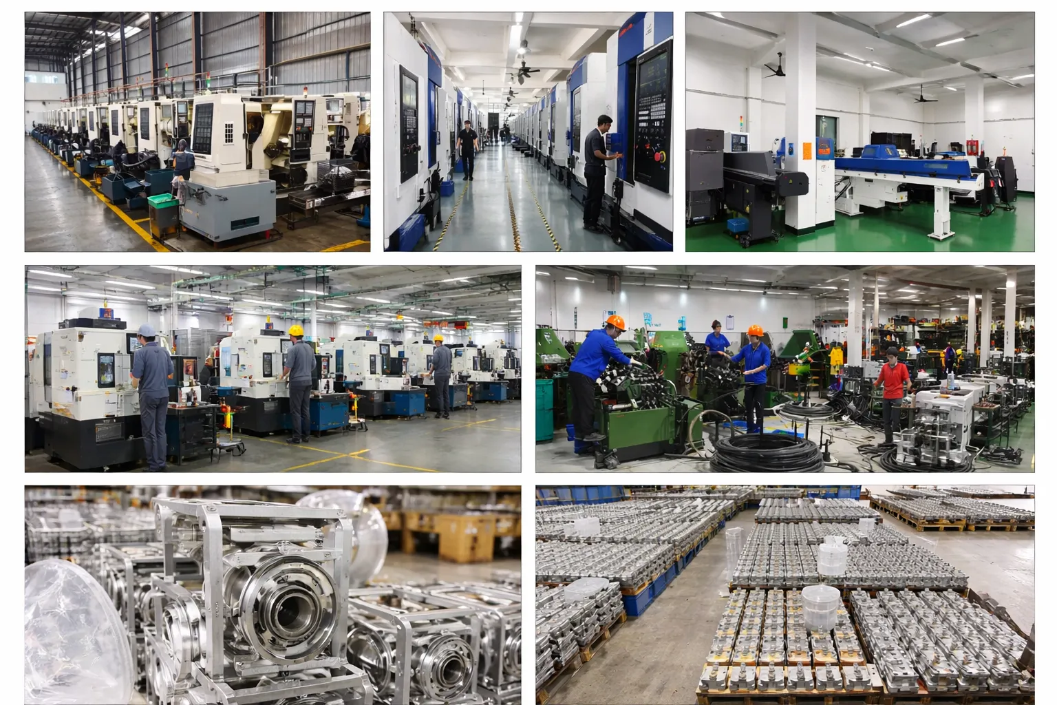
Soporte para la instalación y planos dimensionales
Corea Ever-Power Ofrecemos planos dimensionales en 2D y guías de instalación como estándar para todos los pedidos. Si tiene una orientación de instalación no estándar, un requisito de acoplamiento inusual o una configuración de accionamiento de varias unidades compleja, nuestro equipo de ingeniería puede revisar su plan de instalación antes de comprometerse. Explore nuestra Gama de reductores de engranajes helicoidales o póngase en contacto con nosotros para obtener ayuda con la aplicación.
Editor: Cxm


