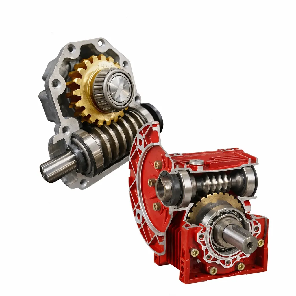
Ussülekande reduktori paigaldamine: inseneri samm-sammult juhend
A correctly installed ussikäigu reduktor ussikäigu reduktor will run for years without problems. The same unit, installed with the common shortcuts that many field teams take, may fail within months — not from product quality, but from installation errors that are entirely avoidable with the right procedure.
Before You Start: Pre-Installation Checks That Cannot Be Skipped
Installation errors are almost always committed in the first 20 minutes, while the installer is still orienting themselves to the unit. A systematic pre-installation check for a ussikäigu reduktor takes under 10 minutes and prevents the majority of commissioning problems.
Unboxing Checklist
☑ Nameplate check: model number, ratio, output shaft configuration match the order
☑ Output shaft diameter and keyway dimensions measured against drawing
☑ Flange/foot bolt hole pattern matches machine interface
☑ No visible cracks in housing, no damaged seals, no damaged shaft surface
☑ Vent plug present and not obstructed (check for shipping tape)
☑ All hardware included: mounting bolts, any specified torque arm bracket
☑ Installation manual or dimensional drawing present
Oil Level Confirmation
Enamik ussiülekande reduktorid are shipped with oil filled ussiülekande reduktorid are shipped with oil filled to the standard horizontal mounting level. Before installation, confirm the ussikäigu reduktor oil level is correct for your intended mounting orientation — different orientations require different fill levels, and using the wrong level is a common cause of early lubrication problems. Refer to the orientation chart in Section 5 of this guide.
Tools Required — and Why the Torque Wrench Is Not Optional
Torque wrench (essential): Under-torqued mounting bolts allow the ussikäigu reduktor housing to flex under load, gradually opening a gap at the mounting face and eventually causing seal leakage. Over-torqued bolts on aluminum housings can crack the boss around the bolt hole. Neither failure is immediately visible — both are completely prevented by using a calibrated torque wrench to the specified values.
Bearing puller / installation tool (essential): Couplings, pulleys, and sprockets must be pressed or pulled onto the worm shaft — never driven with a hammer. Hammer blows transmit shock loads directly into the shaft bearings, fracturing the bearing inner race or permanently increasing bearing clearance. A simple mechanical puller or hydraulic press tool eliminates this completely.
Dial indicator / magnetic base: Required for shaft alignment verification on any direct coupling installation. Alignment errors of more than 0.1 mm radial or 0.05 mm/100 mm angular generate shaft loads that are not included in the bearing selection and will significantly reduce bearing life.
Infrared thermometer: For commissioning temperature monitoring during the trial run procedure. Not needed for the installation itself, but essential for commissioning verification. A basic infrared thermometer ($30–50) is sufficient.
Input End Connection: Motor Coupling
IEC Flange Direct Mount (NMRV Series)
NMRV series ussiülekande reduktorid with IEC flange input accept direct motor mounting without a coupling. The motor shaft inserts into the worm shaft input bore — a keyed connection. Procedure:
1. Confirm the motor shaft diameter matches the reducer input bore (within h6/H7 tolerance).
2. Apply a light film of anti-seize compound to the motor shaft. This prevents corrosion-induced binding during future disassembly.
3. Insert motor shaft into the reducer input bore. The key must fully seat in the keyway. Do not force — if there is resistance, check shaft diameter and keyway alignment before proceeding.
4. Torque the IEC flange bolts in a star pattern to the specified torque (see manufacturer table for M8–M12 bolt sizes).
Flexible Coupling Connection (WP Series)
Radial alignment: Mount a dial indicator on the motor shaft, touching the rim of the coupling half on the ussikäigu reduktor worm shaft. Rotate the motor shaft 360°. Maximum runout: 0.05 mm for standard coupling, 0.02 mm for precision servo coupling.
Angular alignment: Use a feeler gauge at four 90° positions around the coupling gap. Maximum angular deviation: 0.05 mm per 100 mm coupling diameter.
If alignment is outside tolerance: Shim the motor feet or adjust the reducer mounting position. Do not accept misalignment and add flexible coupling element to “absorb” it — flexible elements compensate for thermal expansion, not installation errors.

Belt drive and chain drive input — the suspension load limit: When installing a pulley or sprocket on the worm input shaft, the belt or chain tension exerts a radial force on the shaft. This force is not insignificant — a V-belt on a 100 mm diameter pulley transmitting 2 kW at 1,440 rpm can generate 300–500 N of radial force on the shaft. Check the maximum allowable radial force (Fr₁) for the input shaft in the datasheet and confirm your calculated belt tension is below this limit. Overhung loads beyond Fr₁ will reduce bearing life substantially — sometimes by a factor of 4–8×.
Output End Connection: Driven Equipment
Solid Output Shaft Installation
Mounting sprockets, pulleys, or coupling halves on the solid output shaft of the ussikäigu reduktor follows the same principle as the input end — use a press tool or puller, never a hammer. After seating the component, secure with the shaft end bolt or nut to the correct torque and install a locking washer or thread-locking compound appropriate for the application vibration level.
The output shaft radial load (Fr₂) rating in the datasheet assumes the load is applied at the midpoint of the shaft extension. If the load is applied at the shaft end (maximum overhang), the allowable Fr₂ reduces by 20–30%. Confirm which condition applies to your installation.
Hollow Output Shaft Installation
NMRV series hollow shaft variants slide directly onto the driven equipment shaft — the most common installation for conveyor, agitator, and fan drives. Before installation:
1. Measure the driven shaft diameter. The ussikäigu reduktor hollow bore is typically H7 tolerance — confirm the shaft diameter is within this range (e.g., for a 25 mm bore: 25.000 to 25.021 mm shaft acceptable).
2. Apply a light film of grease to the hollow bore interior and the driven shaft. Without lubrication, the bore and shaft surface will fretting-corrode, making future removal extremely difficult (the assembly can seize permanently).
3. Install the anti-rotation torque arm or bracket as specified. The hollow shaft absorbs torque through the driven shaft key — the torque arm prevents the housing from rotating when torque is applied.
Mounting Position and Oil Level — What Changes with Each Orientation
The mounting position code in the ussikäigu reduktor datasheet (M1–M6 or similar) defines how the unit is oriented. The critical consequence of orientation: the oil fill level must be adjusted to keep the worm gear mesh submerged while preventing oil from reaching and leaking past the shaft seals.
| Paigaldusasend | Description | Oil Level Plug | Special Notes |
|---|---|---|---|
| M1 (standard) | Worm shaft horizontal, output shaft horizontal | Side plug — standard fill | Default catalog condition. Use standard oil volume. |
| M2 / M3 | Worm shaft horizontal, output shaft vertical (up or down) | Top or side plug | Output shaft pointing up: add ~15% more oil. Output shaft pointing down: reduce oil ~10% — risk of overfilling toward lower output shaft seal. |
| M4 / M5 | Worm shaft vertical (up or down), output shaft horizontal | Side plug — adjusted level | Requires manufacturer-confirmed oil volume. Worm shaft seal orientation changes — verify with supplier before filling. |
| M6 | Inverted — output shaft pointing downward | Bottom (now at top) | Vent plug location changes — must confirm vent is at highest point of inverted housing. Oil volume typically reduces by 20%. Confirm with manufacturer. |
The vent plug orientation rule: The vent plug on any ussikäigu reduktor must always be located at the highest point of the installed housing. This ensures that when internal pressure rises during operation, hot air — not oil — exits through the vent. If the unit is installed at a non-standard orientation, confirm the vent plug is repositioned to the highest housing port. On NMRV units, multiple threaded ports are available — one is the oil fill/level plug, one or two others can serve as the vent depending on orientation. Contact Korea Ever-Power if you are unsure which port to use as the vent for a non-standard mounting position.
Mounting Surface Requirements
The mounting surface flatness requirement for any ussikäigu reduktor is not a bureaucratic specification — it is a structural requirement. An aluminum NMRV housing has thin walls by design, allowing it to be lightweight and dissipate heat efficiently. When forced flat against a warped surface by tightened bolts, the housing distorts slightly — causing the bearing bore geometry to change, bearing preload to redistribute unevenly, and the oil seal seating diameter to deviate from round.
The practical mounting surface requirements are:
Flatness: ≤ 0.1 mm per 300 mm of mounting surface length. Check with a straightedge and feeler gauge before tightening. A simple machined steel mounting plate bolted to the machine frame typically meets this requirement; a welded structural plate does not without machining.
If the surface is not flat: Shim the low spots before tightening the ussikäigu reduktor mounting bolts. Stainless steel shim stock in 0.05 and 0.1 mm thicknesses is the correct tool. Do not use washers as shims — they are not flat and simply redistribute the problem.
Trial Run Procedure: The 5-Step Commissioning Sequence
The purpose of the trial run after ussikäigu reduktor installation is to catch installation errors before they become expensive failures. Do not skip stages because the machine is urgently needed — a 2-hour commissioning procedure prevents a 2-week repair.
Step 1: No-Load Run, 30 Minutes
Start the motor with no load on the output shaft. Run for 30 minutes. At 15 and 30 minutes, check and record: housing surface temperature, any noise change from startup, any visible oil seepage.
Pass criteria: Temperature rise ≤ 35°C above ambient (no-load). No irregular clicking, grinding, or high-pitched noise. No active oil leak (light seepage at startup is normal and typically seals within 10 minutes as the seal lip conforms to the shaft).
Step 2: 50% Load, 30 Minutes
Apply 50% of rated ussikäigu reduktor output load. Run for 30 minutes. Repeat temperature and noise checks at 15 and 30 minutes.
Pass criteria: Temperature rise ≤ 45°C above ambient. Noise should not change significantly from no-load (some increase is normal). No new vibration or rattling.
Step 3: Full Load, 1 Hour
Apply the rated ussikäigu reduktor output load. Run for 1 hour. Measure temperature every 15 minutes and confirm it is stabilizing (not still rising after 45 minutes at full load).
Pass criteria: Temperature stabilizes at ≤ 60°C rise above ambient. If temperature is still rising at 45 minutes, this indicates a thermal power limitation — refer to K-05 for corrective action before continuing. Inspect all sealing points for oil after shutdown.
Step 4: Post-Run Inspection
After the full-load ussikäigu reduktor run, while the unit is still warm, inspect: all mounting bolts for looseness (re-torque if needed), all seal points for oil seepage, coupling for unusual wear or misalignment signs.
Slight oil film at shaft seal exits that does not drip actively is acceptable at this stage. Active dripping is not.
Step 5: First Oil Change at 50–100 Hours
This step is not optional and not negotiable. The first 50–100 operating hours generate bronze particles from the worm wheel break-in process. These particles are suspended in the oil and act as abrasives if left in service.
Drain completely while warm, inspect the drained oil (note color and any copper flakes — light bronze tint is normal; heavy copper flakes indicate excessive wear that needs investigation), and refill with fresh oil of the correct grade. After this change, subsequent oil changes follow the standard maintenance interval schedule.
8 Installation Mistakes — Quick Reference
| Mistake | Consequence | Correct Action |
|---|---|---|
| Hammer to install coupling | Bearing inner race fracture | Use bearing puller or press |
| Warped mounting surface | Housing distortion, seal leak | Check flatness, shim if needed |
| Coupling misalignment | Short bearing life | Joondage skaalaindikaatoriga |
| Vale õlitase orientatsiooni jaoks | Määrimisvea või tihendi leke | Kasutage orientatsiooniõli tabelit |
| Ventilatsioonikork on blokeeritud | Rõhu poolt välja surutud tihendid | Veenduge, et ventilatsiooniava on puhas ja üleval. |
| Jäta koormuseta proovikäivitus vahele | Paigaldamise vead | Käivitage alati etapiviisiline kasutuselevõtt |
| Jäta 100h õlivahetus vahele | Abrasiivsed pronksiosakesed kahjustavad võrku | Muutus 50–100 tunni järel ilma eranditeta |
| Kuivõõnesvõlli paigaldus | Võll kiilub avasse jäädavalt kinni | Enne kokkupanekut määrige ava |
Korduma kippuvad küsimused — ussülekande reduktori paigaldamine
Reduktor tarniti õliga täidetud paagis – kas ma pean enne paigaldamist õlitaset kontrollima?
Kas M8 ja M10 poltide puhul on tõesti vaja kasutada momentvõtit – kas ma ei saa neid lihtsalt tunde järgi kindlalt kinni keerata?
Esimeste töötundide jooksul on tunda kerget metallilõhna – kas see on normaalne?
Kuidas eemaldada õõnesvõlli reduktor veovõllilt, kui see on kinni kiilunud?
Pärast paigaldamist on reduktor märgatavalt vaiksem kui tehase vastuvõtukatse ajal – kas see on normaalne?
Kas vertikaalse paigalduse korral, kus sisendvõll on suunatud allapoole, on vaja midagi erilist teha?
Paigaldustugi ja mõõtjoonised
Korea Ever-Power pakub kõigi tellimuste puhul standardvarustuses 2D-mõõtmelisi jooniseid ja paigaldusjuhiseid. Kui teil on mittestandardne paigaldussuund, ebatavaline ühendusnõue või keeruline mitme seadmega ajami konfiguratsioon, saab meie insenerimeeskond enne tellimuse kinnitamist teie paigaldusplaani üle vaadata. Sirvige meie ussikäigu reduktori vahemik või võtke rakenduse toe saamiseks ühendust.
Toimetaja: Cxm


