Funktionsweise eines Schneckengetriebes: Die Mechanik erklärt
The geometry of a Schneckengetriebe determines everything — efficiency, self-locking, noise, and load capacity — before a single bolt is tightened. This guide explains the underlying mechanics that every engineer selecting or specifying a worm gear reducer needs to understand.
Why Understanding the Mechanics Makes You a Better Selector
A catalog page tells you output torque and ratio. It does not tell you why that ratio comes with that efficiency, why the self-locking works up to a certain ratio but not below it, or why two identical-looking Schneckengetriebe from different suppliers with the same specifications can have meaningfully different service lives.
The answers are all in the gear geometry. Once you understand the lead angle, the contact mechanics, and the friction fundamentals, you can read a worm gear reducer datasheet with genuine engineering judgment — not just numbers.

The Worm Pair: Basic Geometry That Drives Everything
A worm gear reducer consists of two primary components: the Schneckenwelle (worm) — a cylindrical screw-like component — and the Schneckenrad — a gear whose teeth are shaped to wrap around the worm thread. The axes of the two components are offset by 90°, and the center distance between them determines the frame size designation.
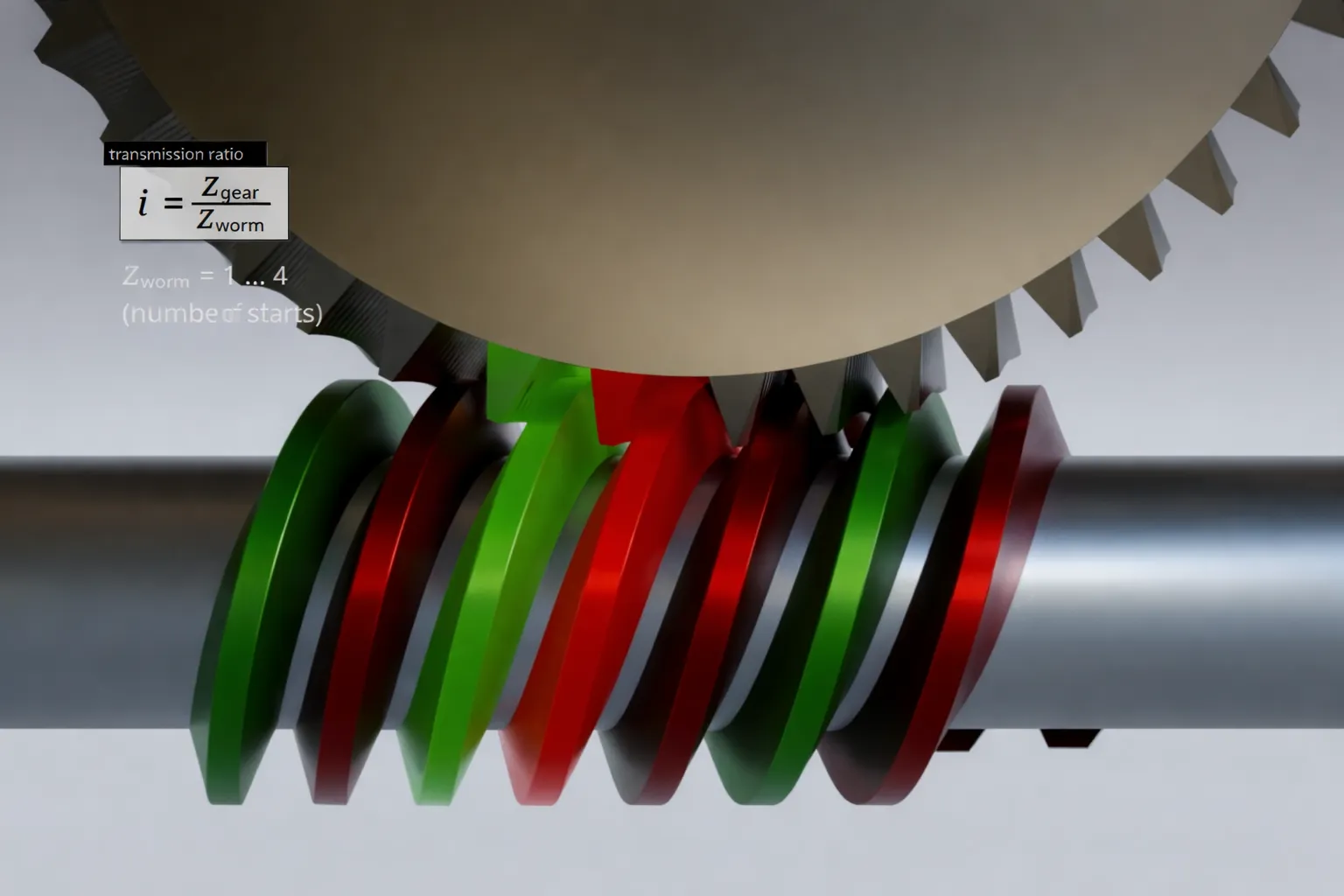
The Worm Shaft
Lead angle (λ): The angle between the worm thread and the plane perpendicular to the worm axis. This is the single most important geometric parameter — it governs efficiency and self-locking simultaneously.
Number of starts (Z₁): How many separate thread spirals the worm carries. A single-start worm (Z₁ = 1) has the smallest lead angle for a given diameter and therefore the highest ratio and strongest self-locking. A four-start worm has a larger lead angle and delivers higher efficiency at the cost of reduced ratio per stage.
Material: 20CrMnTi alloy steel, case-hardened to 58–62 HRC and precision-ground. The hardness advantage over the bronze wheel is deliberate — the worm should not be the sacrificial component.
The Worm Wheel
Number of teeth (Z₂): Directly determines the gear ratio in combination with Z₁. The ratio formula is simply: i = Z₂ / Z₁.
Enveloping tooth profile: Unlike a straight spur gear that contacts at a line, the Schneckenrad teeth are curved to match the worm thread. This creates a curved contact patch rather than a point — distributing load over a larger area and enabling the high torque density that makes Schneckengetriebe effective at large ratios.
Material: High-tin bronze (typically 10–12% tin content). Bronze runs against hardened steel with low friction and acceptable wear — the bronze wheel wears preferentially, which is by design, since wheels are cheaper and easier to replace than worm shafts.
Center Distance = Frame Size
The center distance between worm shaft axis and worm wheel axis — measured in millimeters — defines the frame size. A WP40 has a 40 mm center distance; an NMRV063 has a 63 mm center distance.
Larger center distance → larger wheel diameter → more tooth contact area → higher torque capacity. This is why frame size selection is essentially a torque-driven decision, not a power-driven one.
Lead Angle: The Single Number That Controls Efficiency and Self-Locking
| Lead Angle λ | Typical Ratio i | Approx. η | Self-Lock |
|---|---|---|---|
| 3° – 5° | 60:1 – 100:1 | 40 – 55% | Zuverlässig |
| 6° – 8° | 30:1 – 60:1 | 55 – 70% | Zuverlässig |
| 10° – 15° | 10:1 – 30:1 | 70 – 82% | Marginal |
| 20° – 30° | 5:1 – 10:1 | 83 – 92% | Keiner |
Values at full load, operating temperature, standard mineral oil. Self-locking requires λ < friction angle ρ (typically 6–8° for bronze-on-steel).
The lead angle λ is the helix angle of the worm thread measured at the pitch diameter. Understanding what happens as this angle increases or decreases unlocks every significant property of a Schneckengetriebe.
Think of the worm as an inclined plane wrapped around a cylinder. A shallow inclination (small lead angle) is easy to push a load up but impossible for the load to slide back down — high ratio, self-locking, low efficiency. A steep inclination lets things slide easily in both directions — lower ratio, back-drivable, high efficiency.
This is why no Schneckengetriebe can simultaneously be high-efficiency, high-ratio, and reliably self-locking. The geometry does not allow it — you choose two out of three.
The self-locking condition: A Schneckengetriebe self-locks when the lead angle λ is less than the friction angle ρ = arctan(μ), where μ is the coefficient of friction at the worm-wheel contact. For bronze on hardened steel with mineral oil lubrication, μ ≈ 0.08–0.12, giving ρ ≈ 4.6°–6.8°. At ratio 20:1 and above, most standard worm reducers satisfy this condition. Below 20:1, back-driveability depends on exact geometry and operating temperature — never rely on self-locking without verification below 20:1.
Internal Structure: What Is Inside the Housing

Worm Shaft Bearings
The worm shaft generates significant axial thrust loads in addition to radial loads — the screw geometry pushes the shaft along its axis as it transmits torque. Tapered roller bearings or angular contact bearings are used at the worm shaft ends to handle this combined loading. The preload on these bearings is carefully set at assembly — too loose and shaft deflection increases backlash; too tight and friction losses increase.
Worm Wheel Bearings
The output shaft carrying the worm wheel typically uses deep-groove ball bearings or cylindrical roller bearings for radial loads, and sometimes a thrust bearing at one end. The output bearing capacity determines the maximum Fr₂ (output shaft radial load) and Fa₂ (axial load) specifications you find in the datasheet.
Sealing System
Each shaft exit point uses a lip seal (skeletal oil seal). The seal lip runs against the shaft surface and relies on the lubricant film between lip and shaft for cooling and lubrication. When the seal fails — due to shaft surface roughness, seal lip hardening, or shaft eccentricity from worn bearings — oil begins to escape. This is why bearing wear and seal failure often appear together.
Vent Plug
As the unit heats up during operation, internal air pressure rises. The vent plug allows this pressure to equalize with the atmosphere — preventing oil from being pushed out past the seals. A blocked vent plug is one of the most common and easily overlooked causes of oil seal leakage.
Housing Materials: Aluminum vs Cast Iron — A Real Engineering Choice
| Property | Aluminum ADC12 | Cast Iron HT200 |
|---|---|---|
| Weight (relative) | 1× (lighter) | 2.7× heavier |
| Thermal conductivity | ~160 W/m·K — excellent heat dissipation | ~50 W/m·K — lower dissipation |
| Schlagfestigkeit | Mäßig | High — preferred for shock loads |
| Vibration damping | Niedrig | High — quieter under load |
| Max. frame size | RV/NMRV up to 150 | WP series up to 250+ |
| Best application | Light/medium duty, weight-sensitive, clean environments | Heavy/continuous duty, shock loads, industrial environments |
Aluminum’s higher thermal conductivity is a meaningful practical advantage: the thermal power rating of an aluminum-housed Schneckengetriebe is often 15–25% higher than an equivalent cast iron unit of the same frame size, because the heat generated by friction is dissipated faster. This is why NMRV series aluminum reducers are specified for continuous-duty light industrial applications despite the material’s lower impact resistance compared to cast iron WP series units.
How the Gear Ratio Is Achieved — The Real Mechanism
The gear ratio formula is: i = Z₂ / Z₁ — the number of teeth on the worm wheel divided by the number of starts (threads) on the worm shaft. Each full rotation of the worm shaft advances the worm wheel by Z₁ teeth. If the wheel has 40 teeth and the worm has 1 start, the wheel advances 1/40 of a full rotation for each worm revolution — giving a 40:1 ratio.

1-start worm (Z₁=1): Maximum ratio for given wheel size. Lead angle is minimum. Self-locking most reliable. Efficiency lowest. Used for ratios ≥ 30:1.
2-start worm (Z₁=2): Ratio halved for same wheel size. Lead angle larger. Higher efficiency. Common for 10:1 – 30:1 ratios where efficiency matters more than self-locking reliability.
4-start worm (Z₁=4): Highest efficiency available in a worm design. Lead angle at upper end. Self-locking not achievable. Used for 5:1 – 10:1 ratios where output speed is relatively high.
This explains why a Schneckengetriebe at 40:1 has lower efficiency than one at 10:1 even from the same manufacturer — they use different worm start configurations with different lead angles, not simply a different quality of manufacturing.
Right-Hand vs Left-Hand Spiral: When It Matters
Standard Schneckengetriebe use a right-hand worm helix — when the worm shaft rotates clockwise (viewed from the input end), the output shaft rotates in a specific direction determined by the helix direction. For most industrial applications, right-hand worm reducers are standard and no specification is needed.
Left-hand worm reducers become relevant in two situations: when the required output shaft rotation direction cannot be achieved by repositioning the motor or changing the motor rotation direction, and in back-to-back twin reducer configurations where output shafts must counter-rotate while sharing a common input shaft.
When specifying a left-hand worm reducer, lead time is typically 2–4 weeks longer than standard, as left-hand worms are not stock items at most manufacturers. Confirm availability before committing this to a machine design. Our Schneckengetriebe-Untersetzungsbereich includes both configurations — contact us with rotation requirements.
Worm Gear Wear Mechanics: Understanding the Bronze-on-Steel Design
The sliding contact at the worm-wheel interface — unlike the rolling contact in helical gear pairs — generates friction heat and wear particles continuously during operation. This is the fundamental reason worm gear reducers have lower efficiency than rolling-contact gear drives.
The three wear modes that affect worm gear reducers:
Adhesive wear (scuffing): Occurs when the lubricant film breaks down — metal-to-metal contact causes microwelding and tearing. This is the most damaging mode and typically appears as parallel scoring marks along the tooth face. Cause: oil film inadequacy from incorrect viscosity, insufficient oil level, or overtemperature.
Abrasive wear: Bronze particles from normal worm wheel break-in re-enter the mesh and act as abrasives. This is why the first oil change at 50–100 hours is not optional — these particles must be flushed out before they complete a second cycle through the mesh.
Pitting fatigue: Subsurface fatigue cracks develop under repeated stress cycling, eventually causing surface material to spall off. This is a life-limiting mode under heavy sustained load rather than a sudden failure — it appears as small pits on the bronze tooth face.

Why bronze wears instead of steel — and why that is correct design: The hardened steel worm shaft at HRC 58–62 is approximately 3–4× harder than the tin bronze worm wheel. When the lubrication film is marginal, the softer bronze yields first. This is intentional — a worm wheel replacement costs a fraction of a worm shaft replacement, and the worm shaft geometry (with its precision ground thread) is much harder to manufacture. Correct lubrication keeps both components within their designed wear rate, extending the worm wheel’s service life to 15,000–25,000 hours in standard-duty applications.
Frequently Asked Questions — Worm Gear Reducer Mechanics
Why does a worm gear reducer use bronze for the wheel instead of a harder material?
Can a worm gear reducer be back-driven — from the output shaft?
Why do two worm gear reducers with identical specifications from different suppliers have such different prices?
What is a multi-start worm and when should I specify one?
What is an enveloping worm, and does Korea Ever-Power supply them?
How does running temperature affect the self-locking behavior of a worm gear reducer?
Need Application Engineering Support?
Korea Ever-Power’s technical team works with OEM engineers and procurement professionals across Korea and the region. Whether you are specifying a Schneckengetriebe for a new machine design or replacing an existing unit, we provide dimensional drawings, material certificates, and application support as standard.
Herausgeber: Cxm


