How to Select a Worm Gear Reducer: Engineer’s Guide
A worm gear reducer selected from a catalog page without checking torque, service factor, thermal limits, and IP rating is a scheduled failure — the timing is just unknown. This guide gives you a complete, parameter-by-parameter selection method that works for every industrial application.
What Wrong Selections Cost: Three Real Failures
The most consistent pattern in worm gear reducer failures is not manufacturing defect — it is specification error. Three cases from real installations illustrate the three most common missed parameters.

Case 1: Service Factor Misclassified — Busan Food Packaging Plant
A belt conveyor driving packaged product from filling to cartoning stations, 16 hours per day in a 5°C cold room. The specification team classified the load as “uniform” and applied SF = 1.0. An NMRV050 at 30:1 was ordered. By week two, the housing temperature was regularly reaching 88°C during peak hours. By month three, the output shaft seal started leaking oil onto the belt below. Root cause: frozen product on the belt stiffens the belt substantially at startup — the actual startup torque was 2.3× the calculated running torque, not the 1.0× implied by the uniform load classification. Applying SF = 1.5 to the actual startup condition would have flagged NMRV063 as the correct frame.
Case 2: Thermal Power Limit Ignored — Incheon Chemical Plant
A cast iron WP80 worm gear reducer at 40:1 driving a chemical mixer, 24-hour continuous operation. The mechanical torque rating had 15% margin. After four months, the oil sample showed bronze particles and a dark color. Oil temperature had been running above 100°C. The thermal power rating of WP80 at 40:1 is specified for 20°C ambient. The actual plant ambient was 42°C year-round. At elevated ambient, the catalog thermal power rating drops — the heat generated by the mesh friction had nowhere to go, and the oil thinned and degraded over months. A check of the thermal rating against actual ambient — one calculation — would have indicated a fan-cooled motor or the next frame size was needed.
Case 3: IP Rating vs Actual Environment — Gyeonggi Transplanter
A row-spacing adjustment actuator on an outdoor vegetable transplanting machine, using the same NMRV040 previously used in an indoor greenhouse application. IP55 rated, standard mineral oil. After the first heavy spring rain in Korea, the operator found the adjustment mechanism sluggish. Oil had turned milky-grey from water ingress. The IP55 rating protects against water jets — not against hours of rainfall exposure where cooling creates slight negative pressure inside the housing, drawing moist air past a fatigued seal. Upgrading to IP65 seals and synthetic oil resolved the problem.
Each of these failures involved a parameter that exists in every product catalog. None required specialist knowledge to evaluate. The process described in the rest of this guide eliminates all three failure modes before the order is placed.
Seven Parameters Every Worm Gear Reducer Selection Requires
These seven inputs define a complete specification. If any one is unknown or estimated rather than calculated, the selection has an unresolved risk. Each parameter is described below with the method to determine it — not just what it is, but how to find it for your specific application.
1. Required Output Torque (N·m)
For rotary drives: T = P × 9550 / n_out, where P is shaft power in kW and n_out is the required output speed in rpm. For linear drives (conveyor belt, chain): T = F × r, where F is the effective force in Newtons and r is the drum or sprocket radius in meters. Always calculate peak torque — the startup or maximum load condition — not just the steady running average.
2. Required Output Speed (rpm)
Read from the process requirement directly. For a belt conveyor: n_out = belt speed (m/s) / (π × pulley diameter (m)) × 60. For a mixing shaft: the required mixing rpm is the target. This number must be a real operating requirement — not what feels approximately right. The selected ratio will be calculated from this speed and the motor speed.
3. Motor Input Speed (rpm)
Read from the motor nameplate. A standard 4-pole, 50 Hz induction motor runs at approximately 1,450 rpm under full load (not 1,500 rpm synchronous). This 3.3% difference affects the calculated ratio by the same margin. Using 1,450 rpm for ratio calculations gives a more accurate result than using the synchronous speed. For VFD applications, use the base frequency speed as the reference.
4. Load Type Classification
This determines the service factor. Uniform load: centrifugal pumps, fans, smooth belt conveyors. Moderate shock: screw conveyors, lightly loaded mixers, variable-load conveyors. Heavy shock: crushers, compressors, reciprocating machinery, agricultural equipment. The classification should reflect the worst-case condition the drive will regularly experience, not the typical condition.
5. Mounting Configuration
Foot-mounted (base plate, solid shaft output), flange-mounted (IEC B5/B14 motor flange + separate mounting), hollow shaft (output slides onto driven shaft — no coupling needed), or torque arm (hollow shaft + reaction arm, no base plate). Configuration determines which product series and which catalog model applies — specifying mounting before selecting a model avoids ordering the wrong variant.
6. Environmental Conditions
Ambient temperature range (this affects both thermal rating and lubricant viscosity), humidity and dust level, chemical exposure (fertilizers, cleaning agents, oils), and whether washdown occurs. These determine: housing material (aluminum vs cast iron), seal IP rating (IP54/IP55/IP65/IP67), lubricant type (mineral vs synthetic), and any special surface treatments. Environmental conditions are what converts a catalog spec into a real-world fit.
7. Required Speed Ratio
Calculated as: i = n_input / n_output (e.g., 1,450 / 29 = 50:1). Select the nearest standard available ratio — standard values are 7.5, 10, 15, 20, 25, 30, 40, 50, 60, 80, and 100:1. If the exact calculated ratio falls between standards, round up (to a lower output speed) unless the application is speed-critical, in which case use a VFD to trim the output. Ratios of 20:1 and above are self-locking for most worm gear configurations.

Service Factor Selection — The Parameter Most Often Applied Incorrectly
The service factor (SF) is a multiplier applied to the calculated output torque before the worm gear reducer frame size is selected. It corrects for the difference between a steady-state catalog test and the actual varying, impulsive load the reducer experiences in service. Apply it before frame selection — not as a check after the fact.
Design torque = Calculated torque × Service Factor
| Load Type (Examples) | ≤ 8 hr/day | 8 – 16 hr/day | > 16 hr/day |
|---|---|---|---|
| Uniform — centrifugal pumps, fans, smooth conveyors (warm belt, uniform product) | 1.00 | 1.25 | 1.50 |
| Moderate shock — screw conveyors, loaded mixers, variable load conveyors, cold belt startup | 1.25 | 1.50 | 1.75 |
| Heavy shock — crushers, hoists (starts under load), reciprocating machinery, agricultural equipment | 1.50 | 1.75 | 2.00 |
| Very heavy shock — hammers, press feeders, mining drives with full-load starts | 1.75 | 2.00 | 2.50 |
For VFD-driven applications where soft start is actively controlled, you may apply the lower end of the SF range for the load type — the VFD limits the startup torque spike that heavy shock SF values are designed to absorb. For direct-on-line starts (DOL), always use the upper end.
Reading the Model Code: What the Numbers and Letters Mean
The model code of a worm gear reducer contains all the information needed to confirm the configuration before ordering. Understanding the designation system also makes it much easier to compare catalog models, identify replacement equivalents, and spot errors in purchase orders. These naming conventions apply consistently across all worm gear reducer series produced by Korea Ever-Power.
NMRV / RV / MRV Series (Aluminum Housing)
| Element | Meaning | Example Values |
|---|---|---|
| N | IEC-normalized motor flange | NMRV = flange input; RV = shaft input |
| RV | Right-angle, aluminum housing | Base designation |
| Size number | Centre distance in mm | 025, 030, 040, 050, 063, 075, 090, 110, 130, 150 |
| Optional suffix | VS = worm shaft extension; F = output flange | NMRV050-VS, RV063-F |
WP Series (Cast Iron Housing)
| Element | Meaning | Example Values |
|---|---|---|
| WP | Worm gear, cast iron housing | Base designation |
| W | Worm gear type (always W) | — |
| Configuration | O=standard, DK=double keyed, KO=vertical, KT=torque arm | WPWO, WPWDK, WPWKO |
| Frame size | Housing size number | 40, 50, 60, 70, 80, 90, 100, 120, 135, 155, 175, 200, 250 |
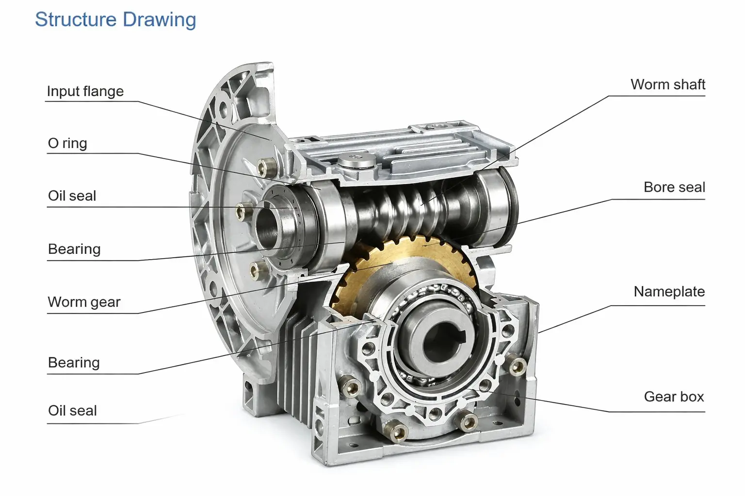
Worm gear reducer structural drawing — shows the worm shaft, wheel, housing, and output shaft configuration that model codes describe
The ratio and motor flange code are appended as separate designation elements. A complete specification reads as: NMRV050 / 40:1 / 63B14 — meaning a normalized aluminum NMRV housing, 50 mm centre distance, 40:1 ratio, 63 mm B14 IEC flange input. All three elements must match the application requirement, not just the size number.
The Six-Step Selection Process
Follow these steps in sequence. Skipping ahead to step 6 (installation check) without completing steps 4 and 5 (thermal verification) is where the majority of incorrect selections originate.
Calculate T & n
Determine required output torque (N·m) and output speed (rpm) from the process requirement
Apply Service Factor
Classify load type, read SF from table, multiply: T_design = T × SF
Calculate Ratio
i = n_input / n_output. Round to nearest standard ratio. Check self-locking requirement (≥ 20:1)
Choose Housing & Series
Aluminum (NMRV/RV) for light-medium and weight-sensitive; cast iron (WP) for heavy, high ambient temp, or impact loads
Verify Thermal Power
P_heat = P_input × (1 – η). Confirm P_heat < P1th (catalog thermal rating at actual ambient temp.) — most common missed check in worm gear reducer selection
Confirm Install & IP
Check shaft overhang load vs rated Fr/Fa, confirm IP rating matches environment, verify dimensional fit
Steps 5 (thermal verification) and 6 (installation confirmation) are the steps most often skipped on time-pressured projects. Both can be completed in under 10 minutes with the catalog data. Both are responsible for approximately 60% of worm gear reducer field failures that return for warranty or replacement discussion.
Eight Selection Mistakes That Show Up Repeatedly in Failure Analysis
These errors appear consistently across industry sectors and company sizes. Each one has a simple correction.
Applying SF = 1.0 by default. Every drive application has some deviation from ideal steady load. Using SF = 1.0 on applications other than verified steady-state uniform loads understates the peak torque the reducer will experience. Even a smooth conveyor starting under load deserves SF = 1.25.
Confusing mechanical torque rating with thermal power rating. A worm gear reducer may have the mechanical rating to handle the torque at that ratio, but if the generated heat exceeds the housing’s ability to dissipate it, the oil degrades and seals fail well before the gear teeth wear. Check both numbers separately.
Using synchronous motor speed (1,500 rpm) instead of actual speed (1,450 rpm). The 3.3% difference in the speed ratio calculation makes the selection one standard ratio step off. This sounds minor but matters when the required output speed is a specific value and the wrong ratio delivers 3% too fast.
Not checking axial and radial shaft loads from overhung sprockets. A chain sprocket mounted directly on the output shaft creates a combined radial and axial load on the output shaft bearing. If this load exceeds the rated Fr value in the datasheet, the bearing fails prematurely — typically looking like a random bearing failure rather than an installation error.
Selecting an aluminum NMRV for high ambient temperature or continuous heavy load. Aluminum housing worm gear reducers have lower thermal mass than cast iron. When ambient temperature is above 30°C and the load approaches rated capacity continuously, the cast iron WP series worm gear reducer is the more reliable choice because of its higher heat capacity and surface area.
Choosing too low a ratio when self-locking is needed. A 15:1 or 20:1 ratio sits at the borderline of self-locking and will not reliably hold position at operating temperature. For any application that depends on self-locking — inclined conveyor, hoist, adjustment mechanism — specify 30:1 or higher as the minimum.
Accepting IP55 for applications with direct water exposure. IP55 resists water jets in any direction. Outdoor applications in rainfall, agriculture applications during irrigation, and food equipment during high-pressure cleaning routinely expose reducers to conditions beyond IP55. Specify IP65 or IP67 when the machine environment includes direct sustained water exposure.
Over-specifying precision class in automation applications. Specifying VRV030 Class AR (0.066° backlash) when Standard class (0.24°) translates to under 0.003 mm of linear positioning error at the lead screw — far better than the application’s tolerance — adds cost without adding performance. Use the backlash calculation to justify the class needed, not conservative instinct.
Worm Gear Reducer Series — Quick Reference for Application Matching
This table maps series characteristics to application types for quick initial screening. Detailed selection should still follow the seven-parameter process above — use this table to identify which series to start with, not to confirm the final specification. For a complete specification sheet on any worm gearbox series listed below, request the technical datasheet when contacting Korea Ever-Power. Browse the full worm gear reducer range for complete specifications.
| Series | Housing | Power Range | Ratio Range | Max Torque | IP | Best For |
|---|---|---|---|---|---|---|
| NMRV 025–150 | Aluminum | 0.06–7.5 kW | 7.5:1–100:1 | ~1,500 N·m | IP55/65 | Light-medium conveyor, food, packaging, agricultural equipment (IEC motor flange input) |
| RV / MRV 025–150 | Aluminum | 0.06–7.5 kW | 7.5:1–100:1 | ~1,500 N·m | IP55 | Same as NMRV, solid shaft input — for non-IEC motors, engines, coupling-connected drives |
| XRV050 | Alu + SS hub | 0.06–2.2 kW | 7.5:1–100:1 | ~450 N·m | IP67 | Washdown, outdoor, slaughterhouse, carwash, coastal environments |
| VRV030 | Aluminum | 0.04–2.2 kW | 5:1–100:1 | ~600 N·m | IP54 | Precision automation, servo axis, stepper motor drives (3 backlash grades) |
| WP 40–155 (WPWO) | Cast iron | 0.12–15 kW | 10:1–60:1 | ~5,600 N·m | IP55 | Heavy industrial, mining, hoists, high ambient temperature, continuous heavy load |
| WPEX (double-stage) | Cast iron | 0.12–15 kW | Thousands:1 | ~5,000 N·m | IP55 | Very low output speed: textile, glass annealing, chemical paddle drives |
How to Request a Selection Quotation — and Get an Accurate Answer Fast
A complete inquiry that includes all seven parameters for a worm gear reducer receives a confirmed selection recommendation within one business day. An incomplete inquiry triggers a series of clarification questions that delay the response by 2 to 5 business days. Sending the following information in one message saves time for both parties:

Minimum Information for a Selection Quotation:
• Machine / application name and brief description
• Required output torque (N·m) — at rated operating condition
• Required output speed (rpm) — or belt/shaft speed with pulley diameter
• Motor power (kW) and speed (rpm) from nameplate
• Daily operating hours and load type (uniform / moderate / heavy)
• Ambient temperature range (°C min / max)
• Environment: indoor / outdoor / washdown / chemical / food
• Required mounting: foot / flange / hollow shaft / torque arm
• Any dimensional constraints (max overall size if relevant)
• Self-locking required: yes / no
• Quantity (for pricing — single prototype or production volume)
Send this information to Korea Ever-Power and include any existing installation drawings if a dimensional match to an existing hole pattern or shaft is required. If you are replacing a unit currently in service, the nameplate data from the existing unit is a useful starting point — but the original spec should be rechecked against the actual current duty, not assumed to have been correct.
Frequently Asked Questions — Worm Gear Reducer Selection
How do I calculate the thermal power limit at my actual ambient temperature?
Can I use one model for multiple different applications in a machine?
What ratio should I select if my calculated ratio falls between two standard values?
Is a hollow shaft output always better than a solid shaft output?
How do I confirm if a replacement unit is compatible with my existing installation?
What is the difference between aluminum and cast iron housing at the same frame size?
Does running a worm gear reducer with a VFD require any special specifications?
What documentation is typically required for OEM product qualification?
Ready to Select Your Worm Gear Reducer?
Send us the seven parameters from this guide and we will confirm the correct worm gear reducer model, ratio, and documentation package within one business day. As a specialist worm gear reducer manufacturer, we support both standard catalog orders and custom engineering specifications.
Editor: Cxm


